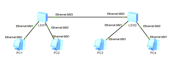
应用场景:两台物理交换机(同段)之间的telnet访问 SW2 可以 以AAA验证方式登录到SW1的VRP系统
已经配置好了交换机的vlanif 2端口ip (两台都在同段)
配置Telnet登录所用的VTY用户界面的终端属性,指定VTY 0\~4这5条VTY虚拟通道可以用于登录
[SW1]user-interface vty 0 4
[SW1-ui-vty0-4]idle-timeout 20 //设置超时间为20分钟
[SW1-ui-vty0-4]history-command max-size 20 //设置历史命令缓冲区的大小为20
配置Telnet登录VTY用户界面的AAA验证方式和用户类别
[SW1-ui-vty0-4]authentication-mode aaa
[SW1-ui-vty0-4]user privilege level 15
[SW1-ui-vty0-4]q
配置控制通过Telnet访问交换机的用户ACL策略
[SW1]user-interface maximum-vty 5 //设置VTY用户界面的最大个数
[SW1]acl 2001
[SW1-acl-basic-2001]rule permit source xxx //配置仅允许IP地址xx的主机访问
[SW1-acl-basic-2001]q
[SW1]user-interface vty 0 4
[SW1-ui-vty0-4]acl 2001 inbound //在VTY 0-4这5个用户界面中应用上面的ACL
创建用于Telnet登录AAA验证的用户名和密码
[SW1]aaa
[SW1-aaa]local-user huawei password cipher hello@123 //设置用户密码
[SW1-aaa]local-user huawei service-type telnet //设置该用户的服务类型为telnet
[SW1-aaa]local-user huawei privilege level 15 //生效级别设置的15
开启Telnet服务器功能,并设置端口
[SW1]telnet server enable
[SW1]telnet server port 1028
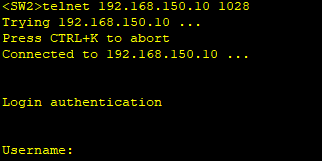
测试结果查看,在SW2测试telnet交换机SW1
]]>要求:某公司在北京设有总部并且在重庆设置分部。公司希望两个区域的员工可以通过私网路由互相访问。在网络边缘设备上使用BGP协议将私网路由发送给运营商,同时需要保证网络信息的安全性。R1,R2,R3,R4属于AS100模拟运营商。运营商内部使用OSPF协议实现IGP互通。在R1,R4建立MP-IBGP邻居,使用MPLS VPN技术使两个区域通过私网路由互访。
首先配置好各个路由器的接口地址以及路由器的环回口地址
在R1上创建实例:
在R1上创建VPN实例1,并将实例1和接口G0/0/0绑定。需注意,在接口上进行实例的绑定后,原配置IP地址会清空,需要重新配置IP地址。
VPN实例用于将VPN私网路由域公网路由隔离,不同VPN实例中的路由也是相互隔离的。
在实例中需要配置RD值和RT值,RD用于区分每个VPN实例的VPN路由,最好保证RD值全网唯一,保证路由在公网传递时不冲突;RT值用于控制VPN路由信息的接收和发布。
在R4上创建实例:
在R1上配置ospf:
在R2上配置ospf:
在R3上配置ospf:
在R4上配置ospf:
在R5上配置ospf:
在R6上配置ospf:
在R1上查看邻居关系:
可以观察到,R1与R2,R5成功建立OSPF邻居关系。
在R1上配置mpls:
在R2上配置mpls:
在R3上配置mpls:
在R4上配置mpls:
在R1上配置BGP:
在R1与R4之间使用环回口建立IBGP邻居关系。
在R4上配置BGP:
在R1上查看BGO vpnv4邻居关系:
在R1上路由引入:
在R1上将实例中的路由引入进BGP中,通过Vpn4路由向外通告,并将BGP的路由引入进OSPF实例下。由于BGP协议可承载的路由条目更多,为了防止后期引入路由条目过多,设备的负载压力过大,使用路由控制,只引入重庆分公司的路由。
在R4上路由引入:
在R4上将实例中的路由引入进BGP中,通过Vpn4路由向外通告,并将BGP的路由引入进OSPF实例下。由于BGP协议可承载的路由条目更多,为了防止后期引入路由条目过多,设备的负载压力过大,使用路由控制,只引入北京总公司的路由。
在R1上查看标签交换路径:
可以观察到,在R1上有AS100内所有的32位环回口地址的FEC,并且为北京总公司的网络生成Vpnv4标签
在R5上查看路由:
可以观察到,R5通过OSPF学习到重庆分公司的6.6.6.6/32的路由。
本路由在R4上通过Vpnv4路由传递给R1,并在R1的OSPF实例下引入BGP路由学习到。
首先配置各个路由器及接口ip地址
R1:
[R1-ospf-1]dis this
[V200R003C00]
#
ospf 1 router-id 1.1.1.1
area 0.0.0.0
network 10.1.1.1 0.0.0.0
network 10.123.12.1 0.0.0.0
#
return
R2:
[R2-ospf-1]dis this
[V200R003C00]
#
ospf 1 router-id 2.2.2.2
area 0.0.0.0
network 10.123.12.2 0.0.0.0
network 10.123.23.2 0.0.0.0
network 20.1.1.1 0.0.0.0
#
return
R3:
[R3-ospf-1]dis this
[V200R003C00]
#
ospf 1 router-id 3.3.3.3
area 0.0.0.0
network 10.123.23.3 0.0.0.0
network 10.123.34.3 0.0.0.0
network 30.1.1.1 0.0.0.0
#
return
R4:
[R4-ospf-1]dis this
[V200R003C00]
#
ospf 1 router-id 4.4.4.4
area 0.0.0.0
network 10.123.34.4 0.0.0.0
network 10.123.45.4 0.0.0.0
network 40.1.1.1 0.0.0.0
#
return
R5:
[R5-ospf-1]dis this
[V200R003C00]
#
ospf 1 router-id 5.5.5.5
area 0.0.0.0
network 10.123.45.5 0.0.0.0
#
return
在R9上检查路由表
在R1上配置MPLS
在R2上配置MPLS
在R3上配置MPLS
在R4上配置MPLS
在R1上配置静态LSP
R1作为ingress设备在去往40.1.1.1/32和 10.123.45.0/24网络时打上标签,同时作为egress设备,当收到标签为201或者205时弹出标签进行路由转发。
[R1]static-lsp ingress 1to4 destination 40.1.1.1 32 nexthop 10.123.12.2 out-labe
l 104
[R1]static-lsp ingress 1to45 destination 10.123.45.0 24 nexthop 10.123.12.2 out-
label 105
[R1]static-lsp egress 4to1 incoming-interface g0/0/0 in-label 201
[R1]static-lsp egress 45to1 incoming-interface g0/0/0 in-label 205
在R2上配置静态LSP
R2作为Transit设备进行标签的交换。
[R2]static-lsp transit 1to4 incoming-interface GigabitEthernet 0/0/0 in-label 10
4 nexthop 10.123.23.3 out-label 204
[R2]static-lsp transit 1to45 incoming-interface GigabitEthernet 0/0/0 in-label 1
05 nexthop 10.123.23.3 out-label 205
[R2]static-lsp transit 4to1 incoming-interface GigabitEthernet0/0/1 in-label 301
nexthop 10.123.12.1 out-label 201
[R2]static-lsp transit 45to1 incoming-interface GigabitEthernet0/0/1 in-label 30
5 nexthop 10.123.12.1 out-label 205
在R3上配置静态LSP
R3作为Transit设备进行标签交换。
[R3]static-lsp transit 1to4 incoming-interface GigabitEthernet 0/0/0 in-label 20
4 nexthop 10.123.34.4 out-label 304
[R3]static-lsp transit 4to1 incoming-interface GigabitEthernet0/0/1 in-label 401
nexthop 10.123.23.2 out-label 301
[R3]static-lsp transit 1to45 incoming-interface GigabitEthernet 0/0/0 in-label 2
05 nexthop 10.123.23.3 out-label 305
[R3]static-lsp transit 45to1 incoming-interface GigabitEthernet0/0/1 in-label 40
5 nexthop 10.123.23.2 out-label 305
在R4上配置静态LSP
R4与R1类似,同样既作为ingress设备又作为egress设备。作为ingress设备在去往40.1.1.1/32和 10.123.45.0/24网络时打上标签,同时作为egress设备,当收到标签为201或者205时弹出标签进行路由转发。
[R4]static-lsp egress 1to4 incoming-interface g0/0/0 in-label 304
[R4]static-lsp egress 1to45 incoming-interface g0/0/0 in-label 305
[R4]static-lsp ingress 4to1 destination 10.1.1.1 32 nexthop 10.123.34.3 out-labe
l 401
在R1上查看标签交换路径:
标签路径中有In/Out Label,在mpls中,Out Label为空时,表示该FEC是由本路由器向上游发布标签,该路由器一般是该FEC的egress设备。In Label是指本路由器为某个FEC分配给对端的Out Label标签,当In Label为空时,表示本路由器是该LSP的最上游路由器,一般是ingress设备。
在R2上查看
在R3上查看
在R4上查看
在R1上Ping测试
右键点击R1设备,选择数据抓包中的G0/0/0接口进行抓包。在R1上带环回口ping测试R4的环回口地址。
进入抓包界面,点击源为10.1.1.1,目的地址为40.1.1.1的数据包查看。我们可以观察到,在数据包中存在MPLS的头部,由此,判断出10.1.1.1访问40.1.1.1走的是MPLS的路径。
]]>本实验模拟企业网络场景,R1为企业总部的网关设备,并且内部有一台服务器,R3连接着企业分公司网关设备,R2为公网ISP设备。一般情况下,运营商只会维护自身的公网路由信息,而不会维护企业内部私网的路由信息,即运营商设备上的路由表中不会出现任何企业内部私网的路由条目。通过配置GRE实现公司总部和分部间私网路由信息的透传及数据通信。
[R1]ip route-static 0.0.0.0 0.0.0.0 10.1.12.2
[R3]ip route-static 0.0.0.0 0.0.0.0 10.1.23.2
可以观察到,跨越了互联网的两个私网网段之间默认是无法直接通信的。此时可以通过GRE协议来实现跨越了互联网的两个私网网段之间的通信。
配置R1、R3的GRE tunnel
在路由器R1、R3上配置GRE Tunnel,使用命令interface tunnel创建隧道接口,指定隧道模式为GRE。配置R1、R3 Tunnel接口的源地址为其S 1/0/0接口IP地址,目的地址为R1/R3的S 1/0/0接口IP地址。还要使用命令ip address配置Tunnel接口的IP地址,注意要在同一网段。
测试R1与目的地址的连通性
检查R1、R3隧道接口状态
检查R1、R3路由表
测试PC1与Server1的连通性,发现还不能联通
配置R1、R3 RIPv2协议
检查R1、R3的RIP邻居
检查R1、R3路由表
测试PC1和Server1的连通性,可以看到已经联通
查看R2的路由表
]]>[S1]stp enable
[S1]stp mode rstp
[S2]stp enable
[S2]stp mode rstp
[S3]stp enable
[S3]stp mode rstp
[S4]stp enable
[S4]stp mode rstp
查看STP的状态和统计信息摘要
在S1上查看STP的状态和统计信息(S1为根桥交换机)
配置S1为主根桥,S2为备份根桥
[S1]stp priority 4096
[S2]stp priority 8192
在另外两台交换机保持默认桥优先级(32768)的情况下,S1拥有最小的桥优先级,S2次之。
再次查看S1上的状态信息(此时S1的桥优先级为4096,并且此时仍然是根桥)
取消S1、S2上手动调整桥优先级的配置,使用stp root命令指定根桥和备份根桥
[S1]undo stp priority
[S1]stp root primary
[S2]undo stp priority
[S2]stp root secondary
查看S1和S2的stp状态信息
S1的桥优先级为0,而S2的桥优先级为4096,此时S1为根桥,S2为备份根桥。
在S4上查看stp状态和统计信息
S4上0/0/2拥有更小的RPC(根路径开销),从而成为根端口
查看S4的0/0/2的STP状态和统计信息
此时路径开销计算方法为Dotlt,接口的STP cost的值为20000
修改S4的0/0/2的STP cost值为40001
[S4]interface g0/0/2
[S4-GigabitEthernet0/0/2]stp cost 40001
[S4-GigabitEthernet0/0/2]
查看s4的STP状态信息
此时0/0/1的RPC为40000,小鱼0/0/2的RPC 40001 S4的0/0/1接口成为根端口
查看S2的STP状态信息
S2上GE0/0/10、GE0/0/11接口收到的BPDU拥有相同的RPC、网桥ID、接口优先级,此时将会比较接收到的BPDU接口ID中的接口编号。
在S1、S2上开启LLDP,查看接口的互联关系
[S1]lldp enable
[S2]lldp enable
[S2]display lldp neighbor brief
S2的GE0/0/10接口对端为S1的GE0/0/10接口,S2的GE0/0/11接口对端为S1的GE0/0/11接口,S2的GE0/0/10接口接收到的BPDU拥有更小的接口编号,这是GE0/0/10成为根端口的原因
在S1上修改GE0/0/11的STP接口优先级,使其发送的BPDU优于 GE0/0/10发送的BPDU
[S1]interface GigabitEthernet 0/0/11
[S1-GigabitEthernet0/0/11] stp port priority 64
STP接口优先级为128,数值越小越优。
再次查看S2的stp状态信息
此时S2的GE0/0/10接口成为根端口。
在所有交换机上创建VLAN10、20、30、40、50、60、70、80,配置MSTP域hcip,并创建两个新的实例:Instance 1、Instance 2,将VLAN10、30、50、70映射到Instance 1,将VLAN20、40、60、80映射到Instance 2,同时将SW1规划为MSTI1的主根桥、MSTI2的备份根桥,将SW2规划为MSTI2的主根桥、MSTI1的备份根桥。
[S1]vlan batch 10 20 30 40 50 60 70 80
[S2]vlan batch 10 20 30 40 50 60 70 80
[S3]vlan batch 10 20 30 40 50 60 70 80
[S4]vlan batch 10 20 30 40 50 60 70 80
将所有的互联接口(S1、S2、S3、S4)配置为Trunk接口,放通所有的(接口端口)Vlan
interface GigabitEthernet0/0/10
port link-type trunk
port trunk allow-pass vlan 10 20 30 40 50 60 70 80
#
interface GigabitEthernet0/0/11
port link-type trunk
port trunk allow-pass vlan 10 20 30 40 50 60 70 80
stp instance 0 port priority 64
#
interface GigabitEthernet0/0/12
port link-type trunk
port trunk allow-pass vlan 10 20 30 40 50 60 70 80
#
interface GigabitEthernet0/0/13
port link-type trunk
port trunk allow-pass vlan 10 20 30 40 50 60 70 80
修改STP模式为MSTP
[S1]stp mode mstp
[S2]stp mode mstp
[S3]stp mode mstp
[S4]stp mode mstp
配置MSTP
[S1]stp region-configuration
[S1-mst-region] region-name hcip
[S1-mst-region] revision-level 1
[S1-mst-region] instance 1 vlan 10 30 50 70
[S1-mst-region] instance 2 vlan 20 40 60 80
[S1-mst-region] active region-configuration
Info: This operation may take a few seconds. Please wait for a moment...done.
[S1-mst-region] quit
/
[S2]stp region-configuration
[S2-mst-region] region-name hcip
[S2-mst-region] revision-level 1
[S2-mst-region] instance 1 vlan 10 30 50 70
[S2-mst-region] instance 2 vlan 20 40 60 80
[S2-mst-region] active region-configuration
Info: This operation may take a few seconds. Please wait for a moment...done.
[S2-mst-region] quit
/
[S3]stp region-configuration
[S3-mst-region] region-name hcip
[S3-mst-region] revision-level 1
[S3-mst-region] instance 1 vlan 10 30 50 70
[S3-mst-region] instance 2 vlan 20 40 60 80
[S3-mst-region] active region-configuration
Info: This operation may take a few seconds. Please wait for a moment...done.
[S3-mst-region] quit
/
[S4]stp region-configuration
[S4-mst-region] region-name hcip
[S4-mst-region] revision-level 1
[S4-mst-region] instance 1 vlan 10 30 50 70
[S4-mst-region] instance 2 vlan 20 40 60 80
[S4-mst-region] active region-configuration
Info: This operation may take a few seconds. Please wait for a moment...done.
[S4-mst-region] quit
在S1上检查MSTP实例和Vlan的映射关系
//配置SW1为MSTI1的根桥、MSTI2的备份根桥
[S1]stp instance 1 root primary
[S1]stp instance 2 root secondary
//配置SW2为MSTI2的根桥、MSTI1的备份根桥
[S2]stp instance 1 root secondary
[S2]stp instance 2 root primary
在S1上查看MST1状态信息
S1上所有接口都是指定接口,S1为MSTI1的根桥
S2上所有接口都是指定接口,S2为MSTI2的根桥。
]]>R2、R3、R4各添加Loopback0 接口
10.123.x.x
//配置R2,激活OSPF
[R2]ospf 1 router-id 10.123.2.2
[R2-ospf-1] area 0.0.0.0
[R2-ospf-1-area-0.0.0.0] network 10.123.2.2 0.0.0.0
[R2-ospf-1-area-0.0.0.0] network 10.123.23.2 0.0.0.0
[R2-ospf-1-area-0.0.0.0] quit
[R2-ospf-1] quit
//配置R3.激活OSPF
[R3]ospf 1 router-id 10.123.3.3
[R3-ospf-1] area 0.0.0.0
[R3-ospf-1-area-0.0.0.0] network 10.123.3.3 0.0.0.0
[R3-ospf-1-area-0.0.0.0] network 10.123.23.3 0.0.0.0
[R3-ospf-1-area-0.0.0.0] network 10.123.34.3 0.0.0.0
[R3-ospf-1-area-0.0.0.0] quit
[R3-ospf-1] quit
//配置R4,激活OSPF
[R4]ospf 1 router-id 10.123.4.4
[R4-ospf-1] area 0.0.0.0
[R4-ospf-1-area-0.0.0.0] network 10.123.4.4 0.0.0.0
[R4-ospf-1-area-0.0.0.0] network 10.123.34.4 0.0.0.0
[R4-ospf-1-area-0.0.0.0] quit
[R4-ospf-1] quit
在R3查看ospf的邻居信息
查看OSPF路由表
//配置R1
[R1]bgp 100
[R1-bgp] router-id 10.123.1.1
[R1-bgp] peer 10.123.12.2 as 64512
//配置R2
[R2]bgp 64512
[R2-bgp] router-id 10.123.2.2
[R2-bgp] peer 10.123.3.3 as-number 64512
[R2-bgp] peer 10.123.3.3 connect-interface LoopBack0
[R2-bgp] peer 10.123.3.3 next-hop-local
[R2-bgp] peer 10.123.12.1 as-number 100
//配置R3
[R3]bgp 64512
[R3-bgp] router-id 10.123.3.3
[R3-bgp] peer 10.123.2.2 as-number 64512
[R3-bgp] peer 10.123.2.2 connect-interface LoopBack0
[R3-bgp] peer 10.123.4.4 as-number 64512
[R3-bgp] peer 10.123.4.4 connect-interface LoopBack0
//配置R4
[R4]bgp 64512
[R4-bgp] router-id 10.123.4.4
[R4-bgp] peer 10.123.3.3 as-number 64512
[R4-bgp] peer 10.123.3.3 connect-interface LoopBack0
[R4-bgp] peer 10.123.3.3 next-hop-local
[R4-bgp] peer 10.123.45.5 as-number 200
//配置R5
[R5]bgp 200
[R5-bgp] router-id 10.123.5.5
[R5-bgp] peer 10.123.45.4 as 64512
//R1
[R1]bgp 100
[R1-bgp] network 172.16.1.0 24
[R1-bgp] network 172.16.2.0 24
[R1-bgp] network 172.16.3.0 24
[R1-bgp] network 172.16.4.0 24
//R5
[R5]bgp 200
[R5-bgp] network 172.16.1.0 24
[R5-bgp] network 172.16.2.0 24
[R5-bgp] network 172.16.3.0 24
[R5-bgp] network 172.16.4.0 24
//创建IP前缀列表1,匹配Loopback1接口路由
[R1]ip ip-prefix 1 permit 172.16.1.0 24 greater-equal 24 less-equal 24
//创建Route-Policy hcip,并创建节点10,在其中调用IP前缀列表1,修改AS_Path属性值
[R1]route-policy hcip permit node 10
[R1-route-policy] if-match ip-prefix 1
[R1-route-policy] apply as-path 300 400 additive
[R1-route-policy] quit
[R1]route-policy hcip permit node 20
//对向BGP对等体R2通告的BGP路由应用Route-Policy
[R1]bgp 100
[R1-bgp] peer 10.0.12.2 route-policy hcip export
//在R1上触发出方向的软复位,刷新对外通告的BGP路由
<R1>refresh bgp all export
在R3上查看BGP路由172.16.1.0/24的信息
此时R3优选R4通告的BGP路由172.16.1.0/24,R2通告的未被优选的原因是AS_Path长度。
创建IP前缀列表1,匹配BGP路由172.16.2.0/24
[R4]ip ip-prefix 1 permit 172.16.2.0 24 greater-equal 24 less-equal 24
创建Route-Policy hcip,并创建节点10,在其中调用IP前缀列表1,修改Local_Preference属性值
[R4]route-policy hcip permit node 10
[R4-route-policy] if-match ip-prefix 1
[R4-route-policy] apply local-preference 200
[R4-route-policy] quit
[R4]route-policy hcip permit node 20
对向BGP对等体R3通告的BGP路由应用Route-Policy
[R4]bgp 64512
[R4-bgp] peer 10.0.3.3 route-policy hcip export
刷新对外通告BGP路由
<R4>refresh bgp all export
在R3上查看BGP路由172.16.2.0/24的明细信息
此时R3优选R4通告的BGP路由172.16.2.0/24,R2通告的BGP路由其Local_Preference值为100,小于R3通告的BGP路由Local_Preference值200,因此R2通告的BGP路由未被优选。
在R2上使得R3优选R5发布的BGP路由172.16.3.0/24
//ip前缀列表1 匹配GBP路由172.16.3.0/24
[R2]ip ip-prefix 1 permit 172.16.3.0 24 greater-equal 24 less-equal 24
创建Route-Policy hcip,并创建节点10,在其中调用IP前缀列表1,修改MED属性值
[R2]route-policy hcip permit node 10
[R2-route-policy] if-match ip-prefix 1
[R2-route-policy] apply cost 200
[R2-route-policy] quit
[R2]route-policy hcip permit node 20
对来自BGP对等体R1的BGP路由应用Route-Policy
[R2]bgp 64512
[R2-bgp] peer 10.0.12.1 route-policy hcip import
在R2刷新接收到的BGP路由
<R2>refresh bgp all import
在R3上配置允许来自不同AS的BGP路由的MED值
[R3]bgp 64512
[R3-bgp] compare-different-as-med
在R3上查看BGP路由172.16.3.0/24的明细信息
R2通告的BGP路由172.16.3.0/24其MED值为200,而R4通告BGP路由MED值为0,R3优选MED值较小的BGP路由,因此R2通告的BGP路由未被优选。
修改R3的路由的pre-value属性的策略,使得R3优选R4通告的BGP路由172.16.4.0/24
创建IP前缀列表1,匹配BGP路由172.16.4.0/24
[R3]ip ip-prefix 1 permit 172.16.4.0 24 greater-equal 24 less-equal 24
创建Route-Policy hcip,并创建节点10,在其中调用IP前缀列表1,修改preferred-value属性值
[R3]route-policy hcip permit node 10
[R3-route-policy] if-match ip-prefix 1
[R3-route-policy] apply preferred-value 300
[R3-route-policy] quit
[R3]route-policy hcip permit node 20
对来自BGP对等体R4的BGP路由应用Route-Policy
[R3]bgp 64512
[R3-bgp] peer 10.123.4.4 route-policy hcip import
R3刷新收到的路由并查看BGP路由172.16.4.0/24的信息
R4通告的BGP路由172.16.3.0/24其preferred-value值为300,而R2通告的preferred-value值为0,R3优选preferred-value值较大的BGP路由,因此R3优选R4通告的BGP路由。
在R1、R5上创建Loopback5接口,将接口路由发布到BGP中,验证Origin属性为IGP的BGP路由优于Origin属性为Incomplete的BGP路由。
R1、R5上创建Loopback5,IP地址为172.16.5.1/24
[R1]interface LoopBack 5
[R1-LoopBack5] ip address 172.16.5.1 24
[R1-LoopBack5] quit
[R5]interface LoopBack 5
[R5-LoopBack5] ip address 172.16.5.1 24
[R5-LoopBack5] quit
在R1、R5上将Loopback5接口路由发布到BGP中,通过network方式
[R1]bgp 100
[R1-bgp] network 172.16.5.0 24
[R5]bgp 200
[R5-bgp] network 172.16.5.0 24
在R3上查看BGP路由表
此时R3上优选R2通告(由R1发布)的BGP路由172.16.5.0/24,此时R2、R4通告的BGP路由Origin属性值都为IGP。
在R1上取消将Loopback5接口路由发布到BGP
创建IP前缀列表2,匹配R1 Loopback5接口路由172.16.5.0/24
[R1]ip ip-prefix 2 permit 172.16.5.0 24 greater-equal 24 less-equal 24
创建Route-Policy origin,并创建节点10,在其中调用IP前缀列表2
[R1]route-policy origin permit node 10
[R1-route-policy] if-match ip-prefix 2
[R1-route-policy] quit
R1上修改为使用import-route direct将直连路由发布到BGP,调用Route-Policy origin限制只引入Loopback5接口路由
[R1]bgp 100
[R1-bgp] import-route direct route-policy origin
在R3上查看BGP路由172.16.5.0/24的明细信息
此时R3优选R4通告的BGP路由172.16.5.0/24。
R2通告(R1发布)的BGP路由172.16.5.0/24此时Origin属性值为incomplete(通过import-route方式发布到BGP),由于Origin属性值原因,该条路由未被优选。
R2、R4之间基于环回口建立IBGP对等体关系,在R2、R3上建立Loopback7接口并将接口路由发布到BGP中,在R4上观察BGP路由优选情况。
R2、R4之间建立IBGP对等体关系
[R2]bgp 64512
[R2-bgp] peer 10.0.4.4 as-number 64512
[R2-bgp] peer 10.0.4.4 connect-interface LoopBack 0
[R4]bgp 64512
[R4-bgp] peer 10.0.2.2 as-number 64512
[R4-bgp] peer 10.0.2.2 connect-interface LoopBack0
检查IBGP对等体关系状态
R2、R4上创建Loopback7接口,并将接口路由发布到BGP
[R2]interface LoopBack 7
[R2-LoopBack7] ip address 172.16.7.1 24
[R2-LoopBack7] quit
[R2]bgp 64512
[R2-bgp] network 172.16.7.0 24
[R3]interface LoopBack 7
[R3-LoopBack7] ip address 172.16.7.1 24
[R3-LoopBack7] quit
[R3]bgp 64512
[R3-bgp] network 172.16.7.0 24
在R4上查看BGP路由172.16.7.0/24的明细信息
R4优选R3发布的BGP路由,其IGP cost为1,小于R2发布的BGP路由IGP cost 2。
R2发布的BGP路由未被优选的原因为IGP cost。
]]>//R2上新添加一个loopback1
ip add 10.2.2.2 24
<R2>ping -c 1 10.123.12.1
PING 10.123.12.1: 56 data bytes, press CTRL_C to break
Reply from 10.123.12.1: bytes=56 Sequence=1 ttl=255 time=220 ms
--- 10.123.12.1 ping statistics ---
1 packet(s) transmitted
1 packet(s) received
0.00% packet loss
round-trip min/avg/max = 220/220/220 ms
<R2>ping -c 1 10.123.23.3
PING 10.123.23.3: 56 data bytes, press CTRL_C to break
Reply from 10.123.23.3: bytes=56 Sequence=1 ttl=255 time=100 ms
--- 10.123.23.3 ping statistics ---
1 packet(s) transmitted
1 packet(s) received
0.00% packet loss
round-trip min/avg/max = 100/100/100 ms
<R2>ping -c 1 10.123.24.4
PING 10.123.24.4: 56 data bytes, press CTRL_C to break
Reply from 10.123.24.4: bytes=56 Sequence=1 ttl=255 time=170 ms
--- 10.123.24.4 ping statistics ---
1 packet(s) transmitted
1 packet(s) received
0.00% packet loss
round-trip min/avg/max = 170/170/170 ms
<R3>ping -c 1 10.123.34.4
PING 10.123.34.4: 56 data bytes, press CTRL_C to break
Reply from 10.123.34.4: bytes=56 Sequence=1 ttl=255 time=40 ms
--- 10.123.34.4 ping statistics ---
1 packet(s) transmitted
1 packet(s) received
0.00% packet loss
round-trip min/avg/max = 40/40/40 ms
R1、R2、R3、R4使用Loopback0接口地址作为Router ID,在各个设备的互联接口、Loopback0接口激活OSPF。
[R1-ospf-1-area-0.0.0.0]dis this
[V200R003C00]
#
area 0.0.0.0
network 10.0.1.1 0.0.0.0
network 10.123.12.1 0.0.0.0
#
return
[R2-ospf-1-area-0.0.0.0]dis this
[V200R003C00]
#
area 0.0.0.0
network 10.0.2.2 0.0.0.0
network 10.123.12.2 0.0.0.0
network 10.123.23.2 0.0.0.0
network 10.123.24.2 0.0.0.0
#
return
[R3-ospf-1-area-0.0.0.0]dis this
[V200R003C00]
#
area 0.0.0.0
network 10.0.3.3 0.0.0.0
network 10.123.23.3 0.0.0.0
network 10.123.34.3 0.0.0.0
#
return
[R4-ospf-1-area-0.0.0.0]dis this
[V200R003C00]
#
area 0.0.0.0
network 10.0.4.4 0.0.0.0
network 10.123.24.4 0.0.0.0
network 10.123.34.4 0.0.0.0
#
return
查看R4的OSPF路由表
可以看出来已经学到了全网路由
bgp 64511
在R2、R3上查看IBGP对等体状态
AS内的IBGP对等体关系成功建立
[R2]bgp 64511
[R2-bgp]peer 10.123.12.1 reflect-client
[R3]bgp 64511
[R3-bgp]peer 10.123.23.2 reflect-client
[R4]bgp 64511
[R4-bgp]peer 10.123.34.3 reflect-client
在本步骤中,我们将在R2上发布BGP路由10.2.2.0/24,并观察该路由依次经路由反射器R3、R4反射后,被通告回R2从而引发潜在路由环路风险的情况。
缺省情况下,R2发布BGP路由后,该路由将被R2直接通告给R4,另一方面也会通过R3反射给R4,此时R4将优选R2直接通告过来的路由,从而不会再将R3反射过来的路由再反射回给R2。为此,我们需要在R2上部署路由策略,使R2不直接向R4通告10.2.2.0/24路由。
//在BGP中调用路由策略
[R2]bgp 64511
[R2-bgp]peer 10.123.24.4 route-policy bgp export
//在R2上发布路由
[R2]bgp 64511
[R2-bgp] network 10.2.2.0 24
在R2、R3上查看BGP路由10.2.2.0/24信息
在R4上查看BGP路由10.2.2.0/24的信息
//让R4重新发送Update报文
<R2>refresh bgp 10.123.24.4 import
查看R2上Update报文收发数量
取消R2上的BGP路由发布
[R2]bgp 64511
[R2-bgp] undo network 10.2.2.0 24
一次查看R1、R2、R3、R4上BGP路由的10.1.1.0/24的信息
R1为BGP路由10.1.1.0/24的始发者,R1将路由通告给了R2(10.0.12.2)
来自路由反射器客户端R1的BGP路由10.1.1.0/24,R2将其反射给了R3(10.0.23.3)
来自路由反射器客户端R2的BGP路由10.1.1.0/24,R2反射时添加了Cluster_List属性,值为10.0.2.2,R3*将该条路由反射给了R4(10.0.34.4)
来自路由反射器客户端R3的BGP路由10.1.1.0/24,R3反射时添加了Cluster_List属性的值,当前值为10.0.3.3,10.0.2.2,R4将该条路由反射给了R2(10.0.24.2)
再次查看R2的BGP路由表
在R2上查看BGP对等体10.123.24.4的详细信息
R2从R4收到了1个Update报文,未向R4发送Update报文(路由策略限制),但是本地BGP路由表中没有R4通告的BGP路由10.1.1.0/24。
在R2上触发入方向的软复位,让R4重新发送Update报文
<R2>refresh bgp 10.123.24.4 import
<R2>display bgp peer 10.123.24.4 verbose | in Update
Update-group ID: 1
Update messages 2
Update messages 0
接收的Update报文数量增加,R2从R4收到了BGP路由10.1.1.0/24的通告。
再次查看R2上BGP路由10.1.1.0 24的明细信息
依旧只有来自R1通告的1条BGP路由,R4通告的BGP路由其Cluster_List属性值中包含了R2的Cluster-ID,R2忽略了该路由通告。
]]>//R2上新添加一个loopback1
ip add 10.2.2.2 24
<R2>ping -c 1 10.123.12.1
PING 10.123.12.1: 56 data bytes, press CTRL_C to break
Reply from 10.123.12.1: bytes=56 Sequence=1 ttl=255 time=220 ms
--- 10.123.12.1 ping statistics ---
1 packet(s) transmitted
1 packet(s) received
0.00% packet loss
round-trip min/avg/max = 220/220/220 ms
<R2>ping -c 1 10.123.23.3
PING 10.123.23.3: 56 data bytes, press CTRL_C to break
Reply from 10.123.23.3: bytes=56 Sequence=1 ttl=255 time=100 ms
--- 10.123.23.3 ping statistics ---
1 packet(s) transmitted
1 packet(s) received
0.00% packet loss
round-trip min/avg/max = 100/100/100 ms
<R2>ping -c 1 10.123.24.4
PING 10.123.24.4: 56 data bytes, press CTRL_C to break
Reply from 10.123.24.4: bytes=56 Sequence=1 ttl=255 time=170 ms
--- 10.123.24.4 ping statistics ---
1 packet(s) transmitted
1 packet(s) received
0.00% packet loss
round-trip min/avg/max = 170/170/170 ms
<R3>ping -c 1 10.123.34.4
PING 10.123.34.4: 56 data bytes, press CTRL_C to break
Reply from 10.123.34.4: bytes=56 Sequence=1 ttl=255 time=40 ms
--- 10.123.34.4 ping statistics ---
1 packet(s) transmitted
1 packet(s) received
0.00% packet loss
round-trip min/avg/max = 40/40/40 ms
R1、R2、R3、R4使用Loopback0接口地址作为Router ID,在各个设备的互联接口、Loopback0接口激活OSPF。
[R1-ospf-1-area-0.0.0.0]dis this
[V200R003C00]
#
area 0.0.0.0
network 10.0.1.1 0.0.0.0
network 10.123.12.1 0.0.0.0
#
return
[R2-ospf-1-area-0.0.0.0]dis this
[V200R003C00]
#
area 0.0.0.0
network 10.0.2.2 0.0.0.0
network 10.123.12.2 0.0.0.0
network 10.123.23.2 0.0.0.0
network 10.123.24.2 0.0.0.0
#
return
[R3-ospf-1-area-0.0.0.0]dis this
[V200R003C00]
#
area 0.0.0.0
network 10.0.3.3 0.0.0.0
network 10.123.23.3 0.0.0.0
network 10.123.34.3 0.0.0.0
#
return
[R4-ospf-1-area-0.0.0.0]dis this
[V200R003C00]
#
area 0.0.0.0
network 10.0.4.4 0.0.0.0
network 10.123.24.4 0.0.0.0
network 10.123.34.4 0.0.0.0
#
return
查看R4的OSPF路由表
可以看出来已经学到了全网路由
bgp 64511
在R2、R3上查看IBGP对等体状态
AS内的IBGP对等体关系成功建立
[R2]bgp 64511
[R2-bgp]peer 10.123.12.1 reflect-client
[R3]bgp 64511
[R3-bgp]peer 10.123.23.2 reflect-client
[R4]bgp 64511
[R4-bgp]peer 10.123.34.3 reflect-client
在本步骤中,我们将在R2上发布BGP路由10.2.2.0/24,并观察该路由依次经路由反射器R3、R4反射后,被通告回R2从而引发潜在路由环路风险的情况。
缺省情况下,R2发布BGP路由后,该路由将被R2直接通告给R4,另一方面也会通过R3反射给R4,此时R4将优选R2直接通告过来的路由,从而不会再将R3反射过来的路由再反射回给R2。为此,我们需要在R2上部署路由策略,使R2不直接向R4通告10.2.2.0/24路由。
//在BGP中调用路由策略
[R2]bgp 64511
[R2-bgp]peer 10.123.24.4 route-policy bgp export
//在R2上发布路由
[R2]bgp 64511
[R2-bgp] network 10.2.2.0 24
在R2、R3上查看BGP路由10.2.2.0/24信息
在R4上查看BGP路由10.2.2.0/24的信息
//让R4重新发送Update报文
<R2>refresh bgp 10.123.24.4 import
查看R2上Update报文收发数量
取消R2上的BGP路由发布
[R2]bgp 64511
[R2-bgp] undo network 10.2.2.0 24
一次查看R1、R2、R3、R4上BGP路由的10.1.1.0/24的信息
R1为BGP路由10.1.1.0/24的始发者,R1将路由通告给了R2(10.0.12.2)
来自路由反射器客户端R1的BGP路由10.1.1.0/24,R2将其反射给了R3(10.0.23.3)
来自路由反射器客户端R2的BGP路由10.1.1.0/24,R2反射时添加了Cluster_List属性,值为10.0.2.2,R3将该条路由反射给了R4(10.0.34.4)
来自路由反射器客户端R3的BGP路由10.1.1.0/24,R3反射时添加了Cluster_List属性的值,当前值为10.0.3.3,10.0.2.2,R4将该条路由反射给了R2(10.0.24.2)
再次查看R2的BGP路由表
在R2上查看BGP对等体10.123.24.4的详细信息
R2从R4收到了1个Update报文,未向R4发送Update报文(路由策略限制),但是本地BGP路由表中没有R4通告的BGP路由10.1.1.0/24。
在R2上触发入方向的软复位,让R4重新发送Update报文
<R2>refresh bgp 10.123.24.4 import
<R2>display bgp peer 10.123.24.4 verbose | in Update
Update-group ID: 1
Update messages 2
Update messages 0
接收的Update报文数量增加,R2从R4收到了BGP路由10.1.1.0/24的通告。
再次查看R2上BGP路由10.1.1.0 24的明细信息
依旧只有来自R1通告的1条BGP路由,R4通告的BGP路由其Cluster_List属性值中包含了R2的Cluster-ID,R2忽略了该路由通告。
]]>冒分十六进制表示法
格式为X:X:X:X:X:X:X:X,其中每个X表示地址中的16b,以十六进制表示 例如:ABCD:EF01:2345:6789:ABCD:EF01:2345:6789 这种表示法中,每个X的前导0是可以省略的
0位压缩表示法
在某些情况下,一个IPv6地址中间可能包含很长的一段0,可以把连续的一段0压缩为“::”。但为保证地址解析的唯一性,地址中”::”只能出现一次 例如
FF01:0:0:0:0:0:0:1101 → FF01::1101 0:0:0:0:0:0:0:1 → ::1 0:0:0:0:0:0:0:0 → ::
内嵌IPv4地址表示法
为了实现IPv4-IPv6互通,IPv4地址会嵌入IPv6地址中,此时地址常表示为:X:X:X:X:X:X:d.d.d.d,前96b采用冒分十六进制表示,而最后32b地址则使用IPv4的点分十进制表示,例如::192.168.0.1与::FFFF:192.168.0.1就是两个典型的例子,注意在前96b中,压缩0位的方法依旧适用
R1-R4的全局和相关接口都使用ipv6功能,同事生成本地链路地址(R1为例)
[R1]ipv6
[R1]int g0/0/0
[R1-GigabitEthernet0/0/0]ipv6 enable
[R1-GigabitEthernet0/0/0]ipv6 address auto link-local
[R1-GigabitEthernet0/0/0]dis this
[V200R003C00]
#
interface GigabitEthernet0/0/0
ipv6 enable
ipv6 address 2001::1/64
ipv6 address auto link-local
#
return
[R2]int g0/0/0
[R2-GigabitEthernet0/0/0]dis this
[V200R003C00]
#
interface GigabitEthernet0/0/0
ipv6 enable
ipv6 address 2001::2/64
ipv6 address auto link-local
#
return
[R2-GigabitEthernet0/0/0]int g0/0/1
[R2-GigabitEthernet0/0/1]dis this
[V200R003C00]
#
interface GigabitEthernet0/0/1
ipv6 enable
ipv6 address 2002::1/64
ipv6 address auto link-local
dhcpv6 server pool1
#
return
[R2-GigabitEthernet0/0/1]int g0/0/2
[R2-GigabitEthernet0/0/2]dis this
[V200R003C00]
#
interface GigabitEthernet0/0/2
ipv6 enable
ipv6 address 2003::1/64
ipv6 address auto link-local
undo ipv6 nd ra halt
#
return
[R2]dhcp enable
[R2]dhcpv6 pool pool1
[R2-dhcpv6-pool-pool1]dis this
[V200R003C00]
#
dhcpv6 pool pool1
address prefix 2002::/64
#
return
[R2-dhcpv6-pool-pool1]int g0/0/1
[R2-GigabitEthernet0/0/1]dis this
[V200R003C00]
#
interface GigabitEthernet0/0/1
ipv6 enable
ipv6 address 2002::1/64
ipv6 address auto link-local
dhcpv6 server pool1
#
return
[R3]dhcp enable
[R3-GigabitEthernet0/0/0]dis this
[V200R003C00]
#
interface GigabitEthernet0/0/0
ipv6 enable
ipv6 address auto link-local
ipv6 address auto dhcp
#
return
[R2-GigabitEthernet0/0/2]dis this
[R2-GigabitEthernet0/0/2]undo ipv6 nd ra halt
[R4]int g0/0/0
[R4-GigabitEthernet0/0/0]dis this
[V200R003C00]
#
interface GigabitEthernet0/0/0
ipv6 enable
ipv6 address auto link-local
ipv6 address auto global
#
return
[R4]ipv6 route-static 2001:: 64 2003::1
[R4]ipv6 route-static 2002:: 64 2003::1
[R1]ipv6 route-static 2002:: 15 2001::2
[R3]ipv6 route-static :: 0 2002::1
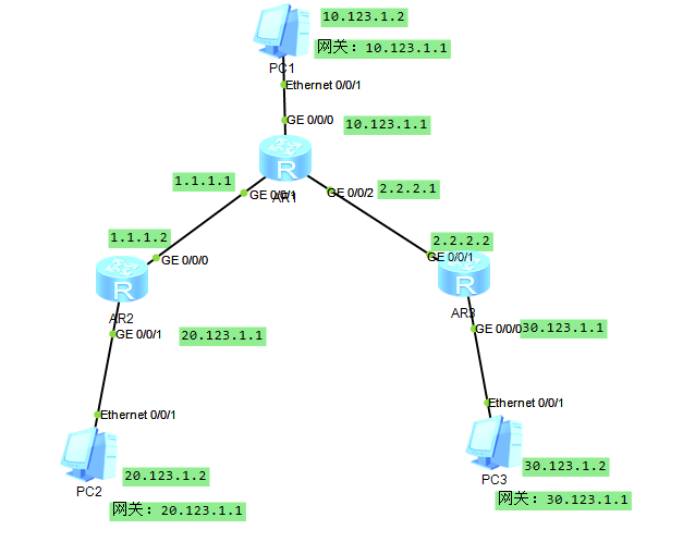
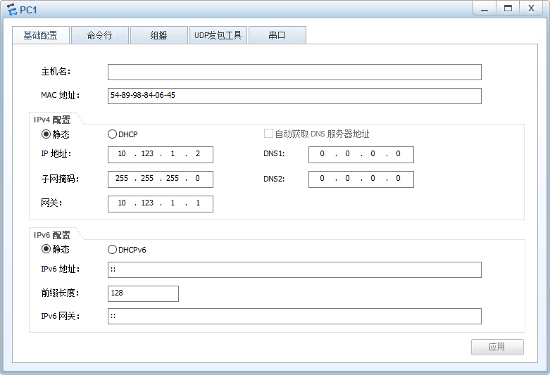
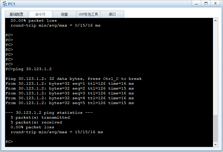
案例要求:需要不通网段的PC1与PC2、PC3主机分别ping通
准备:三台PC端主机、三台路由器(AR2220)
操作:
Switch1:
#
sysname S1
#
vlan batch 10 40 50
#
interface Vlanif40
ip address 10.1.4.2 255.255.255.252
#
interface Vlanif50
ip address 10.1.4.5 255.255.255.252
#
interface Vlanif10
ip address 10.1.1.1 255.255.255.0
#
interface GigabitEthernet0/0/1
port link-type trunk
port trunk allow-pass vlan 10
#
interface GigabitEthernet0/0/2
port link-type trunk
port trunk allow-pass vlan 40
#
interface GigabitEthernet0/0/3
port link-type access
port default vlan 50
#
ip route-static 10.1.2.0 255.255.255.0 10.1.4.1
ip route-static 10.1.3.0 255.255.255.0 10.1.4.6
#
return
Switch2:
#
sysname S2
#
vlan batch 20 40
#
interface Vlanif40
ip address 10.1.4.1 255.255.255.252
#
interface Vlanif20
ip address 10.1.2.1 255.255.255.0
#
interface GigabitEthernet0/0/1
port link-type trunk
port trunk allow-pass vlan 40
#
interface GigabitEthernet0/0/2
port link-type access
port default vlan 20
#
ip route-static 0.0.0.0 0.0.0.0 10.1.4.2
#
return
Switch3:
#
sysname S3
#
vlan batch 30 50
#
interface Vlanif50
ip address 10.1.4.6 255.255.255.252
#
interface Vlanif30
ip address 10.1.3.1 255.255.255.0
#
interface GigabitEthernet0/0/1
port link-type trunk
port trunk allow-pass vlan 50
#
interface GigabitEthernet0/0/2
port link-type access
port default vlan 30
#
ip route-static 0.0.0.0 0.0.0.0 10.1.4.5
#
return
测试连通性(10.1.2.1 ping 10.1.3.1)
]]>