OSPF基础配置实例
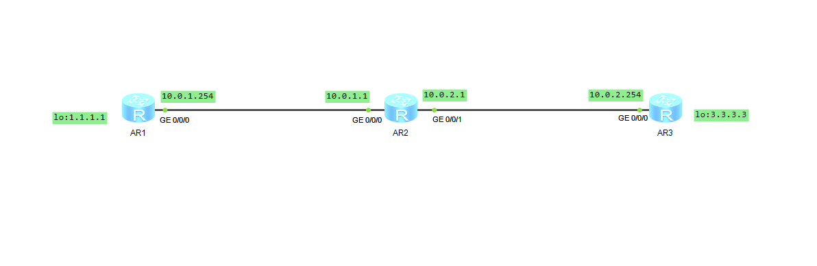
配置简单基础案例如图 有R1、R2、R3 要求使用OSPF 使得R1的1.1.1.1与R3的3.3.3.3互通
配置接口
#配置R1接口
[R1]int GigabitEthernet 0/0/0
[R1-GigabitEthernet0/0/0]dis this
[V200R003C00]
#
interface GigabitEthernet0/0/0
 ip address 10.0.1.254 255.255.255.0
#
return
[R1-GigabitEthernet0/0/0]q
[R1]int LoopBack 0
[R1-LoopBack0]dis this
[V200R003C00]
#
interface LoopBack0
 ip address 1.1.1.1 255.255.255.0
#
return
[R1-LoopBack0]

#配置R2接口
[R2]int GigabitEthernet 0/0/0
[R2-GigabitEthernet0/0/0]dis this
[V200R003C00]
#
interface GigabitEthernet0/0/0
 ip address 10.0.1.1 255.255.255.0
#
return
[R2-GigabitEthernet0/0/0]q
[R2]int GigabitEthernet 0/0/1
[R2-GigabitEthernet0/0/1]dis this
[V200R003C00]
#
interface GigabitEthernet0/0/1
 ip address 10.0.2.1 255.255.255.0
#
return
[R2-GigabitEthernet0/0/1]

#配置R3接口
[R3]int GigabitEthernet 0/0/0
[R3-GigabitEthernet0/0/0]dis this
[V200R003C00]
#
interface GigabitEthernet0/0/0
 ip address 10.0.2.254 255.255.255.0
#
return
[R3-GigabitEthernet0/0/0]q
[R3]int LoopBack 0
[R3-LoopBack0]dis this
[V200R003C00]
#
interface LoopBack0
 ip address 3.3.3.3 255.255.255.0
#
return
[R3-LoopBack0]
配置OSPF
#配置R1 OSPF协议
[R1]ospf 1
[R1-ospf-1]dis this
[V200R003C00]
#
ospf 1 router-id 1.1.1.1
 area 0.0.0.0
  network 1.1.1.1 0.0.0.0
  network 10.0.1.0 0.0.0.255
#
return
[R1-ospf-1]

#配置R2 OSPF协议
[R2]ospf 1
[R2-ospf-1]dis this
[V200R003C00]
#
ospf 1 router-id 2.2.2.2
 area 0.0.0.0
  network 10.0.1.0 0.0.0.255
 area 0.0.0.1
  network 10.0.2.0 0.0.0.255
#
return
[R2-ospf-1]

#配置R3 OSPF协议
[R3]ospf 1
[R3-ospf-1]dis this
[V200R003C00]
#
ospf 1 router-id 3.3.3.3
 area 0.0.0.1
  network 3.3.3.3 0.0.0.0
  network 10.0.2.0 0.0.0.255
#
return
[R3-ospf-1]
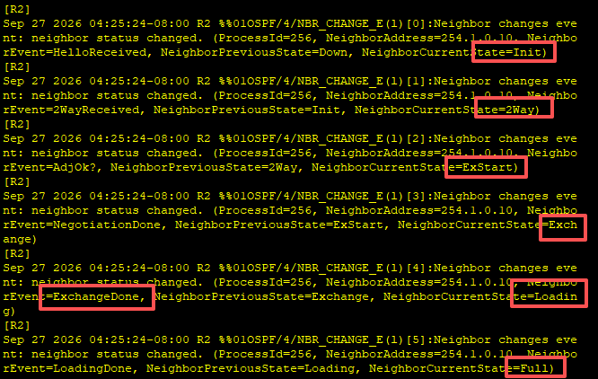
此时配置完成后 会有相关提示 最终有Full 代表邻居建立完成
结果验证
在路由器R2上查看OSPF邻居表 最终状态为Full 代表成功
[R2]dis ospf peer brief

     OSPF Process 1 with Router ID 2.2.2.2
          Peer Statistic Information
 ----------------------------------------------------------------------------
 Area Id          Interface                        Neighbor id      State
 0.0.0.0          GigabitEthernet0/0/0             1.1.1.1          Full
 0.0.0.1          GigabitEthernet0/0/1             3.3.3.3          Full
 ----------------------------------------------------------------------------
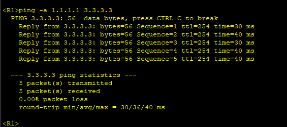
从R1测试是否正常通3.3.3.3 查看正常通信
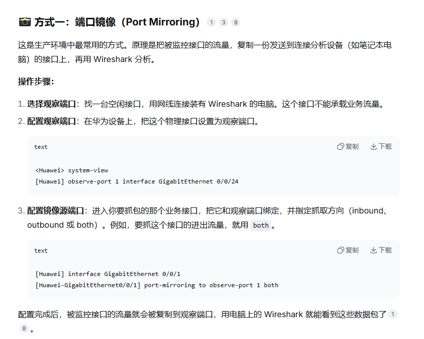
如果不成功 可以从R2路由器的出接口抓包查看
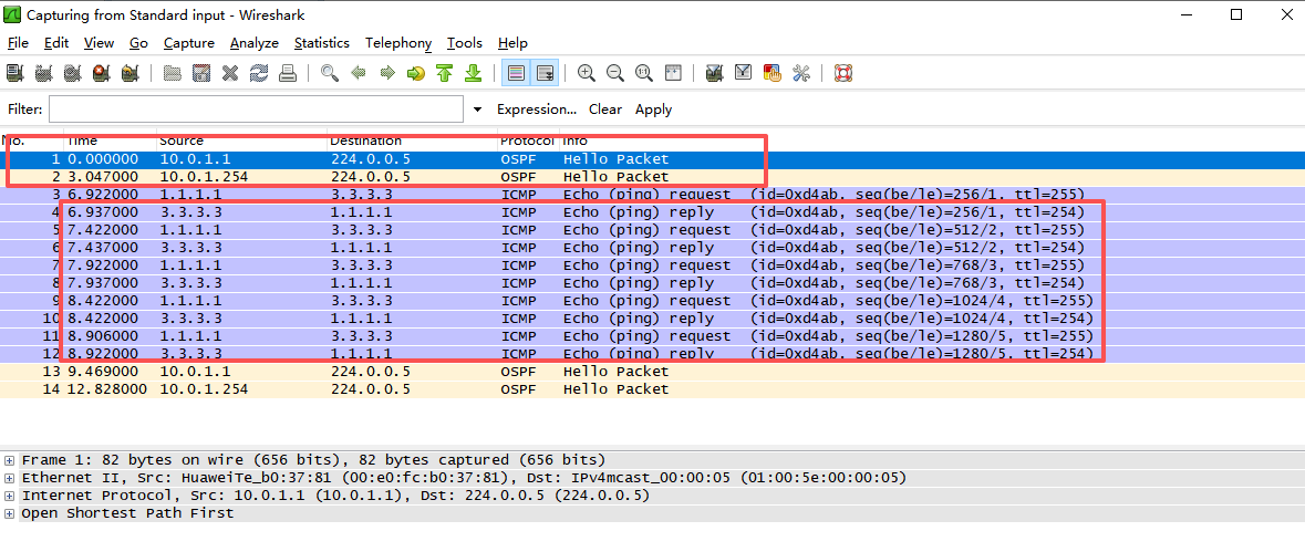
扩展
如果在R1新增10.10.10.10地址 R3新增30.30.30.30地址 让他们两个互通
只需要将新网段宣告进 OSPF
#在 R1 上操作:
<R1> system-view
[R1] ospf 1
[R1-ospf-1] area 0.0.0.0
[R1-ospf-1-area-0.0.0.0] network 10.10.10.0 0.0.0.255   <-- 宣告新网段
[R1-ospf-1-area-0.0.0.0] quit
[R1-ospf-1] quit

在 R3 上操作:
<R3> system-view
[R3] ospf 1
[R3-ospf-1] area 0.0.0.1   <-- 注意:R3 之前配置的是 Area 1
[R3-ospf-1-area-0.0.0.1] network 30.30.30.0 0.0.0.255   <-- 宣告新网段
[R3-ospf-1-area-0.0.0.1] quit
[R3-ospf-1] quit

注意:R2 不需要宣告 10.10.10.0 或 30.30.30.0,它只负责中转
测试结果:
<R1>ping -a 10.10.10.10 30.30.30.30
PING 30.30.30.30: 56 data bytes, press CTRL_C to break
Reply from 30.30.30.30: bytes=56 Sequence=1 ttl=254 time=40 ms
Reply from 30.30.30.30: bytes=56 Sequence=2 ttl=254 time=30 ms
Reply from 30.30.30.30: bytes=56 Sequence=3 ttl=254 time=30 ms
Reply from 30.30.30.30: bytes=56 Sequence=4 ttl=254 time=40 ms
Reply from 30.30.30.30: bytes=56 Sequence=5 ttl=254 time=30 ms
--- 30.30.30.30 ping statistics ---
5 packet(s) transmitted
5 packet(s) received
0.00% packet loss
round-trip min/avg/max = 30/34/40 ms在实际交换机或者路由器内如何使用抓包工具 抓取接口处数据